Results
-


HD Quiz powered by harmonic design

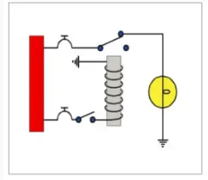
#1. The logic function of the circuit shown is

#2. The circuit shown here represents
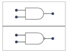
#3. The gate symbols shown are
#4. A gate which requires that all inputs must be HIGH to obtain an output would be:
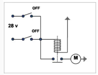
#5. This diagram represents:

#6. To obtain logic ‘0’ at output ‘Z’ there must be
#7. A transistor:
#8. A transistor:
#9. A gate with only one input and one output:
#10. The two most commonly used gates are:
#11. Truth tables illustrate the relationship between
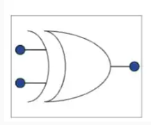
#12. The output expression for this type of gate is:

#13. In order to energise the relay shown in this circuit, the logic state at the inputs must be: